Routing-based Synthesis
Routing-based Synthesis
Routing-based Synthesis is an alternative approach to DMFB compilation that eschews the traditional approach of scheduling, followed by placement and then routing. Routing-based synthesis eliminates the concept of rectangular mixing modules and instead allows droplets to move on the chip on any route during operation execution. Routing-based synthesis converts concurrent mixing operations into a routing problem: mixing droplets can move anywhere on the DMFB as long as they do not inadvertently interfere. As mixing latencies now depend on the routing paths taken, operation latencies are no longer known a-priori, so a schedule must be generated on-demand, rather than computed upfront. This completely changes the underlying algorithmics.
Routing-based synthesis is implemented within the framework, despite the fact that it cannot be naturally decomposed into the three phases as shown above.
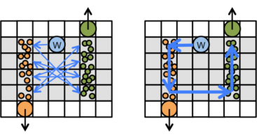
The two images below depict a 2x4 rectangular mixing. A droplet being mixed within a rectangular mixing can take many different cyclic paths, as shown. Experimental work by Richard Fair's lab at Duke has shown that these two cyclic paths lead to optimal mixing times for a 2x4 mixer; other cyclic paths may be sub-optimal and will lead to longer mixing times.
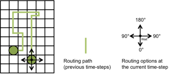
In contrast, routing-based mixing, as shown below, does not restrict the area of movement to a pre-defined rectangular region. At each actuation cycle, the droplet being mixed has five choices: {Stay Still, Move Forward, Turn Left, Turn Right, Move Backward}; each choice has an implication for mixing. In general, moving forward is the best option (greatest contribution to more mixing), followed by turning left or right (mixing occurs, but less effective than moving forward); staying still contributes nothing to the mixing effort, while moving backward can cause a small amount of unmixing.
With many droplets being mixed concurrently on-chip, the objective is to mix as rapidly as possible while staying within the boundaries of the chip and without violating interference constraints. Droplet movements are chosen randomly in a manner that biases the choice of the next droplet movement toward those that yield the greatest contribution to mixing. If we detect any form of deadlock or congestion, we bias the movement probabilities away from further mixing and instead toward backing away from the congested region. This seems to work well enough in practice.
Although the idea is simple and elegant in principle, getting an effective and realistic implementation to work turns out to be much more challenging than one may initially expect. The four key challenges are:
♦ To support efficient wash droplet routing
♦ To support non-routing-based operations that utilize external modules (e.g., heating, detection, etc.)
♦ To prevent deadlock from occurring, especially at I/O ports on the periphery of the chip
♦ To prevent contamination-induced deadlock and trapped droplets
These challenges are interdependent. Several examples of these challenges and how we overcome them are presented next. A detailed description of how we overcame these challenges can be found in the following paper:
S. Windh, C. Phung, D. Grissom, P. Pop, and P. Brisk
Performance Improvements and Congestion Reduction for Routing-based Synthesis for Digital Microfluidic Biochips
IEEE Transactions on Computer-Aided Design of Integrated Circuits and Systems (TCAD)
36(1):41-54, January, 2017
Paper
This paper is an extension to prior work by Paul Pop and Jan Madsen at DTU Compute, Denmark, which introduced the concept of routing-based synthesis:
E. Maftei, P. Pop, and J. Madsen
Routing-based Synthesis of Digital Microfluidic Biochips
Design Automation for Embedded Systems (Springer)
16(1):19-44, March, 2012
Wash Droplet Routing
Routing-based synthesis partitions a DMFB into a set of non-overlapping distinct regions, and allocates one wash droplet per region. That wash droplet is responsible for removing all contamination within that region. Wash droplets have a finite capacity (i.e., it can clean a fixed number of contaminated cells). Once a wash droplet exceeds its capacity, it is routed off-chip and replaced with a new wash droplet. Although simple in principle, several challenging issues can arise.
The first issue is the order in which to wash contaminated cells. An intuitive solution is to wash the cells in the order in which they are contaminated. This makes sense when only one mixing operation occurs in the wash droplet's region; however, when multiple mixing operations happen concurrently, this can can lead to inefficiencies, as shown below (left). A better solution is to wash as much of each contaminated path as possible, as shown below (right).
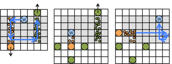
Unfortunately, this approach has its own limitations which are related to deadlock. If each droplet can cleanly exit the wash droplet's region, as shown below (left), then this approach suffices. However, a situation can occur where a droplet is trapped by other droplets just on the outside of the region, as shown below (center). In this case, the wash droplet cannot decontaminate the last cell on the path because doing so would violate droplet interference region constraints; moreover, the wash droplet in its current position contributes to the deadlock. The best option, shown below (right), is for the wash droplet to decontaminate the other path. Moving out of the way alleviates the deadlock, and the wash droplet can remove any additional contamination later.
External Devices
Supporting external devices, such as integrated heaters or detectors, is easy in principle. These devices are fixed at known locations on the chip, and utilizing them is not a mixing or routing-based operation. The principle is similar: route the droplets that need to use the devices directly toward the devices; route all other droplets away from the devices. The details, however, are a bit more complicated.
First, we discovered that pre-computing a direct route from a droplet's current position and then transporting the droplet to the external device, can lead to deadlocks with other droplets. Therefore we adopt the randomized approach to selecting droplet movements, but bias the movements toward the module. This works well enough in practice.
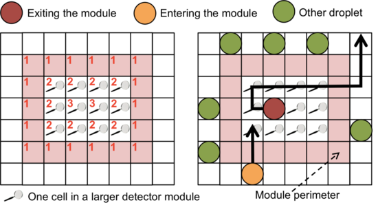
Transporting droplets off of a module is a bit more subtle. As shown below (left), we assign depth values to each electrode on top of an external device, with higher values toward the center. When a droplet needs to move away from the device, the straightforward option is to always move toward a lower depth-value; however, this may not be possible, as shown below (right). Here, droplets on the perimeter of the device prevent a direct path to the exit. Instead, it suffices to allow the droplet exiting the device to move from one electrode to another at the same depth, eventually moving it to the perimeter.
Droplet Input Port Trap
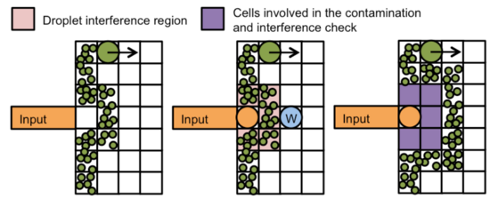
The figure below (left and center) show a situation where an input operation immediately traps a droplet. All electrodes surrounding the droplet are contaminated. As a result, the droplet cannot move. At the same time, the contaminated cells are within the droplet's interference region, so they cannot be washed without violating droplet interference constraints. To prevent this from occurring, we impose the constraint that a droplet may only be input into the chip if the 2×3 region surrounding the input port holds no other droplets and is contamination-free, as shown below (right).
Wash Droplet Input Port Trap
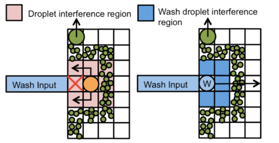
A similar situation can occur near wash droplet input ports. As shown below (left), a droplet is trapped by contamination in the 2×3 region next to the wash droplet input port. The wash droplet cannot enter the chip because doing so would immediately cause a violation of droplet interference constraints. If the wash droplet responsible for the region surrounding the wash input port has already exceeded its capacity, then it will be routed off-chip for disposal; blocking the wash input port prevents its replenishment, as no wash droplet can clean the contaminated cell. The solution, as shown below (right), is to input wash droplets immediately, holding them in-place. Although this renders the 2×3 region next to the input port unavailable to other droplets (i.e., reducing spatial parallelism), it can ensure that this particular situation never occurs.
Output Port Deadlock
Deadlock situations can occur near output ports as well. Although these deadlocks cannot be formally prevented, we can take steps to significantly reduce the likelihood that they occur.
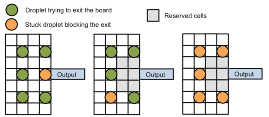
As shown below (left), a situation may occur where one droplet blocks several others that are trying to exit the chip. This situation is difficult to detect and rectify with 100% certainty, because it can scale up to an arbitrary number of droplets in the most general case. An improvement, shown below (center), is to reserve a 2×3 region adjacent; the only droplets that may enter the region are those in the process of exiting the chip; thus, one droplet cannot block the exit; however, as shown below (right), a group of five droplets can collectively cause a similar blockage, although the likelihood of this occurring in practice is much lower than the single-droplet blockage.
Reserving a larger region would increase the number of droplets that can collectively block the exit, further lowering the probability of this occurring, but further restricting the amount of spatial parallelism available. We have found that reserving the 2×3 region in conjunction with dynamically detecting deadlocks and adjusting the droplet movement probabilities in response, works well enough in practice.
Contact
Please direct any questions, comments, or other inquiries to the following e-mail address: microfluidics@cs.ucr.edu
Acknowledgment
This material is based upon work supported by the National Science Foundation under Grant Numbers 1035603, 1536026, and 1545097. Any opinions, findings, and conclusions or recommendations expressed in this material are those of the author(s) and do not necessarily reflect the views of the National Science Foundation.


